 |
Colorado
Pantera
Club |
|
|
|
|
|
|
Rebuilding a Ford 351 Cleveland
Part 6: Assembling The Bottom End
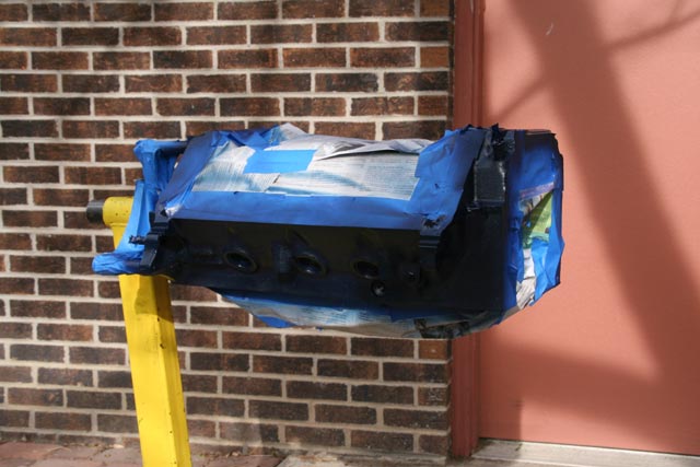
| Paint the block and heads. Lesson learned: do this as soon as you get them back from the machine shop. Otherwise you'll have to sand off a bunch of rust. Be sure to carefully cover and mask all the interior surfaces and any mating surfaces. I used VHT SP125 Ford Dark Blue enamel paint. |
|
 |
|
|
|
|
|
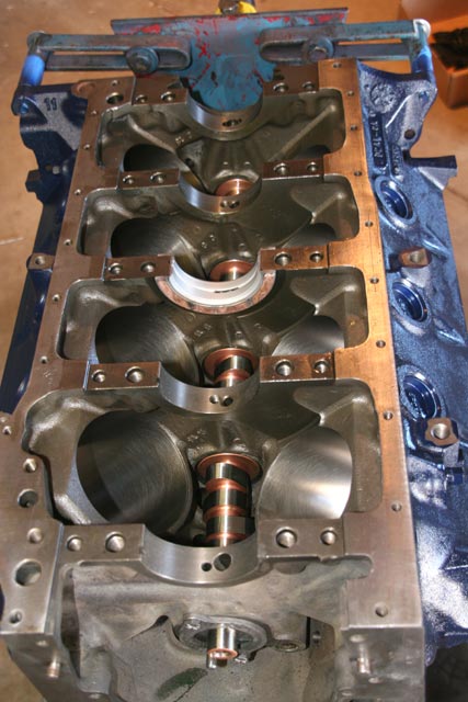
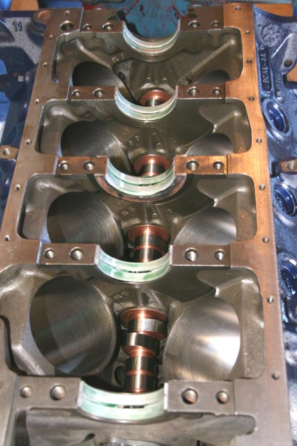
Start from the inside out. Camshaft goes in first - this is so you can carefully guide the cam through the bearings without the crankshaft getting in your way. Be sure to thoroughly lubricate the cam and bearings with assembly lube. Once it's seated in place, install the cam retainer plate. Then you're ready to start seating the main bearing halves (center thrust bearing is seen in the photo here). |
|
 |
|
|
|
|
|
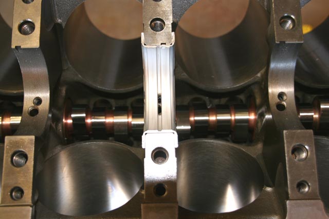
| Thrust bearing close-up. Close-up of the center thrust bearing. This is the #3 bearing. Ford bearings are numbered 1 through 5 starting at the front. Be sure to carefully clean the block journal surface before installing the bearings. Don't let anything get in between the block and the bearing halves. |
|
 |
|
|
|
|
|
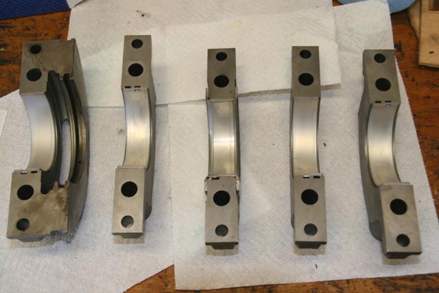
| Prep the main bearing caps. Insert the bearing halves into the main caps. Again, keep everything clean when you do this. |
|
 |
|
|
|
|
|
Bearings ready for the crankshaft. Here we see all the main bearings in place and lubricated with assembly lube. Lube goes between the crank and the bearings, but not between the bearings and the journals. |
|
 |
|
|
|
|
|
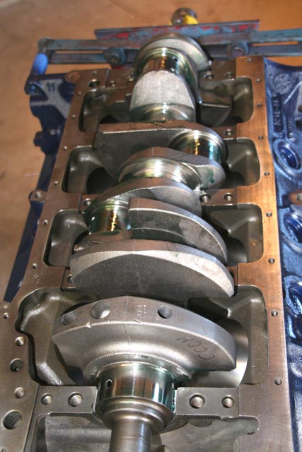
Set crankshaft in place. Note: if you're going to Plastigage the bearings, don't put lube on the surfaces where you're going to put the Plastigage. If you're not going to Plastigage, then lube up the sliding surfaces real good. |
|
 |
|
|
|
|
|
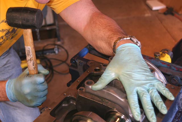
| Install main caps. Set them in place by hand for alignment. Then you'll have to tap them with a soft mallet to get them to "snap" into place. The rear main cap requires special attention since it's got a rubber seal. Follow the seal manufacturer's instructions on that one. Once all the caps are firmly in place, you can start torquing the bolts. |
|
 |
|
|
|
|
|
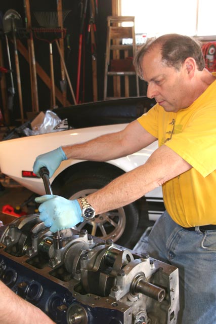
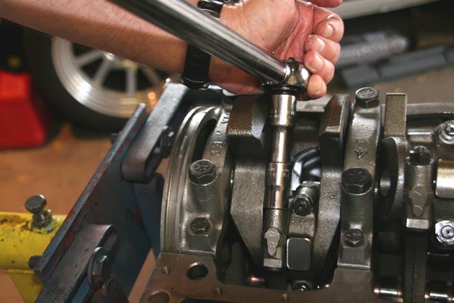
Torque those main bolts! Keith's on the torque wrench here while Jeff and I hold onto the engine stand to keep it from rotating. Main cap bolts need to be torqued in steps (1/3 increments) and in a spiral order starting from the center. Most rebuild books cover this in detail, so I won't get into it here. Be sure to pay special attention to the torquing procedure as this is very important to the stability and long-term reliability of the bottom end. |
|
 |
|
|
|
|
|
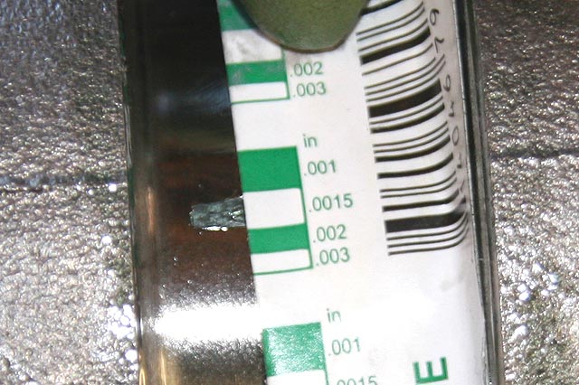
| Check Plastigage. If you've Plastigaged your bearings, remove the main caps after torquing them and take the thickness measurements. Here we see one of mine coming in between 0.0015" and 0.0020" (OK for a street engine). After the Plastigage testing is complete, lube up the sliding surfaces, re-assemble and re-torque everything. |
|
 |
|
|
|
|
|
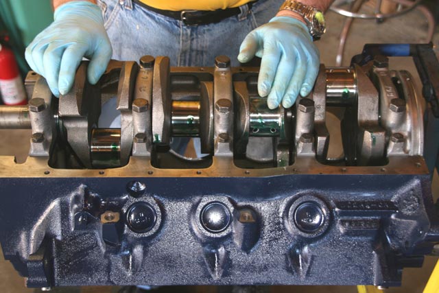
| Crankshaft is in place! With all the caps torqued, the crankshaft is now firmly in place. |
|
 |
|
|
|
|
|
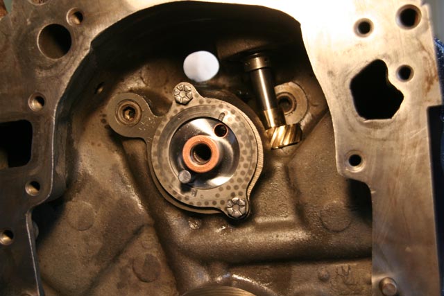
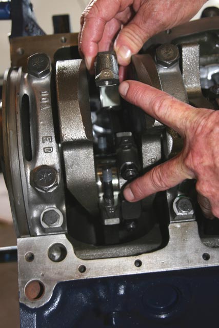
| Check distributor gear clearance. Now is a good time to test-fit the distributor and gear. On the Clevelands, the distributor gear will end up sitting just above a ledge in the block casting. If the gear is located too low on the distributor shaft, it will rub on this ledge and wear out. With the distributor body snugged down, there should be a little bit of clearance between the bottom of the distributor gear and the block ledge. |
|
 |
|
|
|
|
|
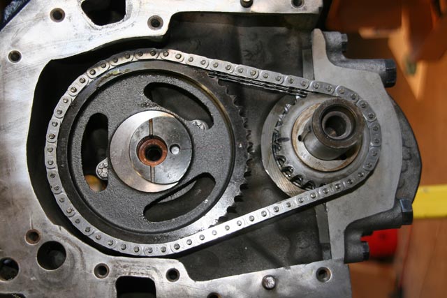
| Install timing set. The only thing to watch is how you align the crank sprocket. The cam sprocket will have a mark which should point straight towards the crank sprocket. Most crank sprockets are stamped with alignment marks in three locations on the sprocket. Typically, one is 4 degrees retarded, one is at 0 degrees, and one is 4 degrees advanced. I installed it at the standard 0 degree setting, which means the center mark on the crank sprocket aligns with the mark on the cam sprocket. |
|
 |
|
|
|
|
|
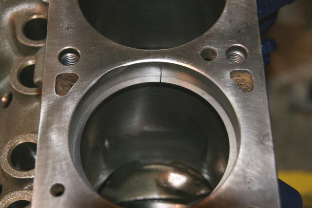
Let's talk about rings. Now it's time to start looking at our pistons and rings. I bought file-to-fit rings. Start by sliding a ring into the cylinder bore you intend to install it in. Chances are it will be too tight. You'll need to file the end edges slowly and carefully until you can put it in the cylinder bore and measure the proper gap between the ends. It's important you have the ring square in the bore and about 1/2" deep. |
|
 |
|
|
|
|
|
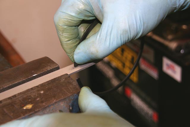
| File the rings to the proper gap. This is a slow and tedious process, but a very important one to get right. Rings are filed to a specific end gap to allow for thermal expansion of the steel during engine operation. Too little gap will cause the ends of the ring to smash into each other and the ring will start to twist, eventually causing failure. Too much gap will lose compression. So take your time and do it right. File slowly and check the gap frequently. Once the material is gone, you can't get it back! |
|
 |
|
|
|
|
|
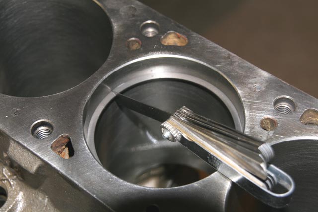
| Checking ring gap. During the filing process, frequently re-check the end gap in the cylinder bore which you intend to install each ring. Keep rings in order by cylinder number so you know which ones are assigned to which cylinders. |
|
 |
|
|
|
|
|
| Install oil rings. These consist of three pieces: two identical retainer rings (shown here) and a flexible expander ring. Walk the rings on carefully to avoid scratching the piston. The expander ring ends should point towards the rear of the engine. The top and bottom retainer rings should have their ends offset about 1" from the expander end. The instructions will likely give you some other tips on how to install these. Pay close attention and make sure the oil rings are properly seated in the piston groove. |
|
 |
|
|
|
|
|
| Install compression rings. Use a ring expander tool to make this job simple. Lower ring goes on first. Upper ring should be marked with a dot which should face up. Ring gaps should point towards the front of the engine, but they should be offset from one another so that there is not a single line path for combustion gas flow to pass through. Follow the instructions that come with the ring kit and double check everything. |
|
 |
|
|
|
|
|
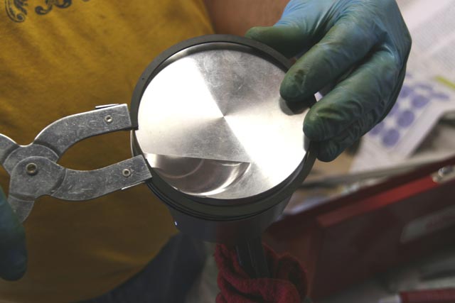
| Compress the rings for installation into the cylinder bores. Use a ring compressor tool to accomplish this. Carefully slide the ring compressor over the piston/ring assembly. Then slowly tighten the clamp. |
|
 |
|
|
|
|
|
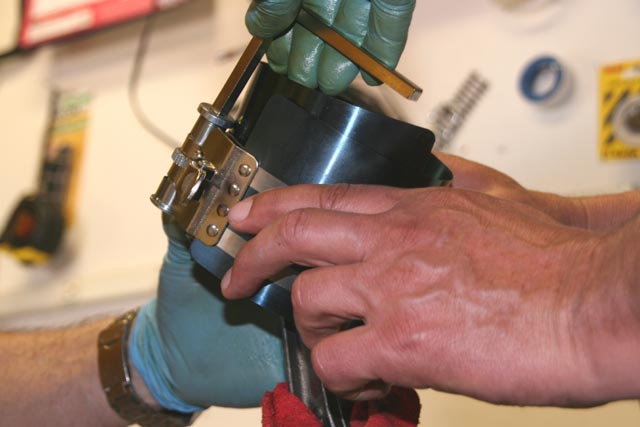
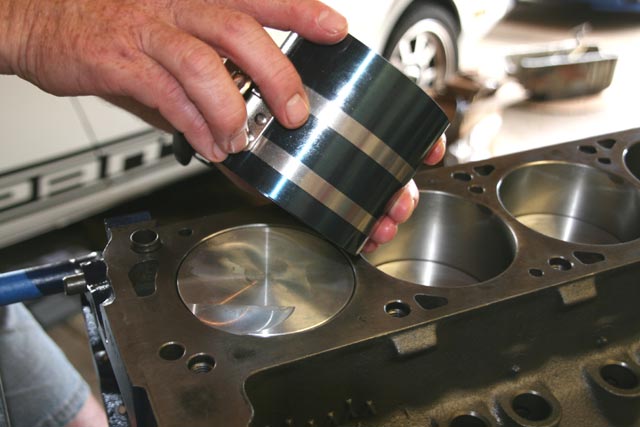
| Check the ring compressor. Make sure the rings are compressed evenly around the piston circumference. Also make sure the piston is square in the compressor. Tighten the clamp snug and then it's time to start installing pistons. |
|
 |
|
|
|
|
|
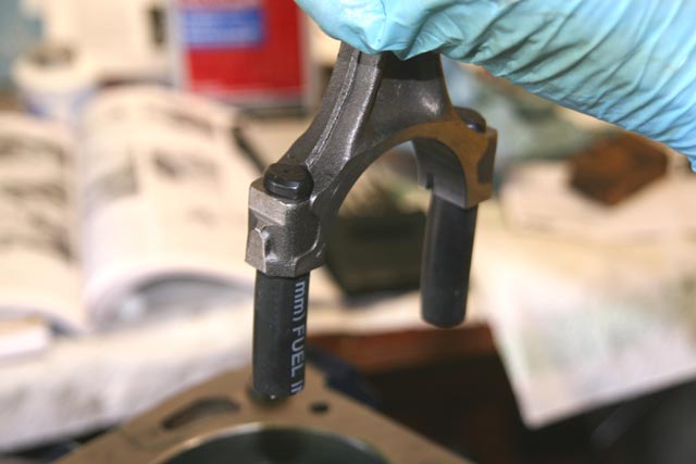
| Cover the rod bolts. Before you slam those new pistons in, be sure to cover the rod bolts with something to keep them from gouging your crank journals. Fuel hose works great. You can also buy fancy rod bolt condoms if you want to look like a pro. Don't forget to install the bearing halves in the bottom of the rods. |
|
 |
|
|
|
|
|
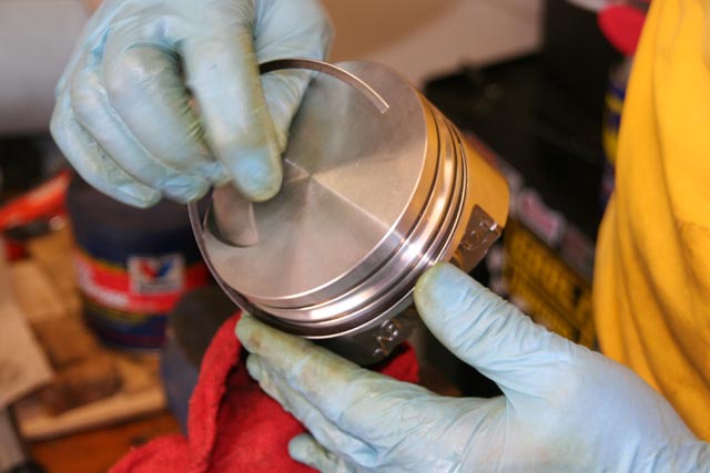
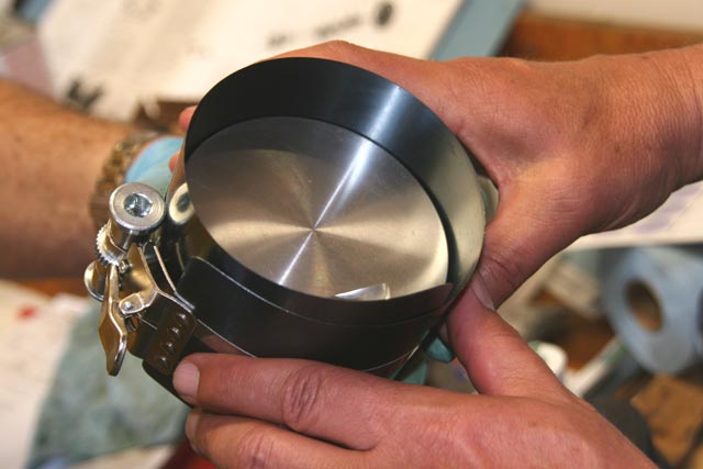
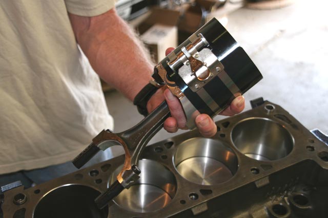
| Piston is ready for installation in the block. Don't forget to pay attention to which way the piston needs to face. Pistons with a valve relief generally need the relief to line up under the intake valves. Now is the time to throw some lube on the crankshaft rod journals. |
|
 |
|
|
|
|
|
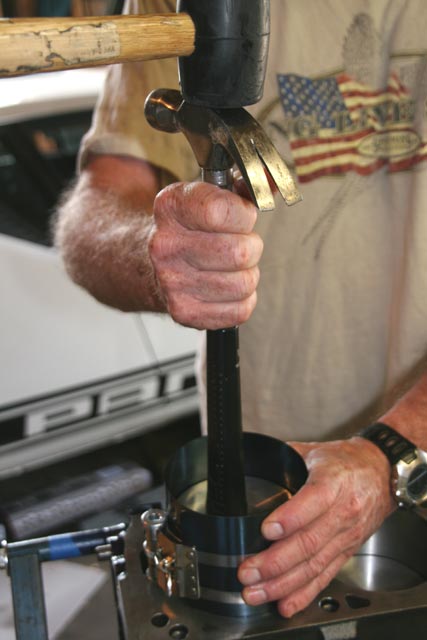
Tap piston into block. This procedure is a little more tricky than it looks. Set the piston base squarely into the cylinder bore. Then use something with a soft end (like the rubber grip on a hammer as shown here) as a punch and tap the piston down into the bore. Having two sets of hands helps a lot here. One person needs to put downward pressure on the compressor tool while stabilizing the hammer. The other person can then gently tap the piston in with the rubber mallet as shown here. Don't be surprised if a ring pops out and it takes several attempts to get everything in. If a ring pops out, remove the piston/ring, reset the compressor tool, and try it again. Take your time and do it right. |
|
 |
|
|
|
|
|
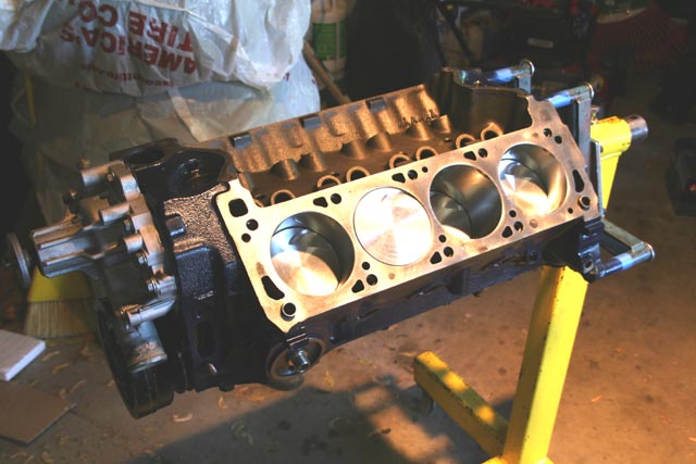
| Success! We've got all our pistons pushed in. |
|
 |
|
|
|
|
|
Install rod caps. Don't forget to make sure they have their bearing halves in place. The caps are matched to each rod and are stamped with the rod number on them. Make sure you get the right caps on the right rods. |
|
 |
|
|
|
|
|
| Torque the rod cap bolts. If you're using aftermarket high-strength bolts then you'll probably need a higher torque than the factory bolts. Check the instructions that came with the bolts. After everything is torqued, check your rod cap side clearances. The rods should slide freely axially along the crank journals without much resistance. |
|
 |
|
|
|
|
|
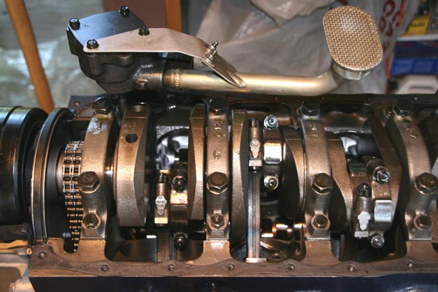
Start bolting stuff to the block. Now that the hard work is done on the block, you can start installing the "easy" stuff. This includes the front cover, damper, water pump, fuel pump, etc. Don't forget the little oil slinger that slides onto the crankshaft in front of the timing chain.
Be sure to cover the block with a bag when you're not working on it so that dirt and crud won't fall in. |
|
 |
|
|
|
|
|
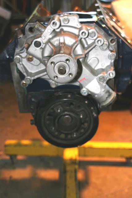
Water pump and front cover. Pay attention when you're installing the water pump as there are several different lengths of bolts used and they all have specific locations where they need to go. Pay extra special attention to the two horizontal bottom bolts that go through the front cover plate. If they're too long, they could hit your timing chain. |
|
 |
|
|
|
|
|
| Oil pump / oil pan. Bolt on the oil pump and its drive shaft. Make sure the pump driveshaft has the retaining clip on the top end of it so it can't be lifted out of the oil pump socket during operation. Install the oil pan seals per the manufacturer's recommendations. Take one last look at the bottom end and bolt the oil pan on. |
|
 |
|
|
|
|
|